Mold Inspection Consulting and Remediation Organization
Since 2006
close menu

Triplett TEV500 Pro Electric Vehicle Charger Test Kit

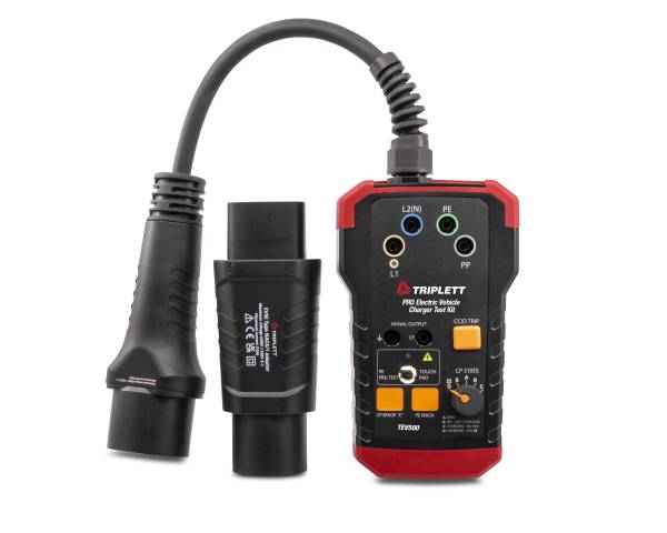
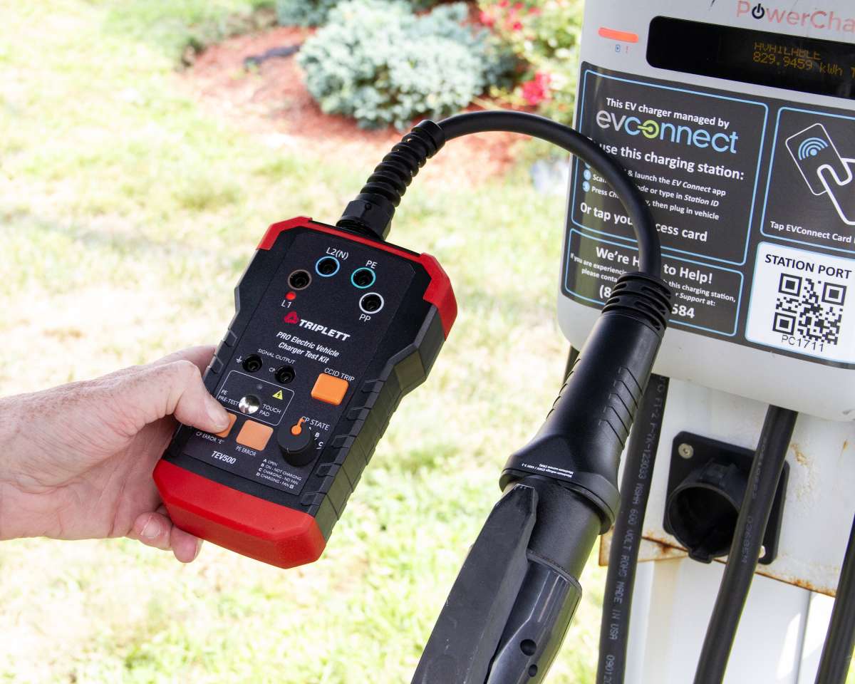
The Triplett Model TEV500 PRO Electric Vehicle Charger Test Kit tests charging stations using basic & advanced diagnostics.

More info

Triplett TEV500 Pro Electric Vehicle Charger Test Kit
Roll over image to zoom Click image to expand
  • Triplett TEV500 Pro Electric Vehicle Charger Test Kit
  • Triplett TEV500 Pro Electric Vehicle Charger Test Kit
  • Triplett TEV500 Pro Electric Vehicle Charger Test Kit
  • Triplett TEV500 Pro Electric Vehicle Charger Test Kit
  • Triplett TEV500 Pro Electric Vehicle Charger Test Kit

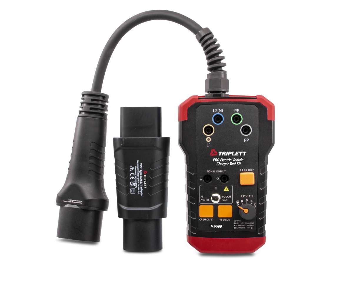
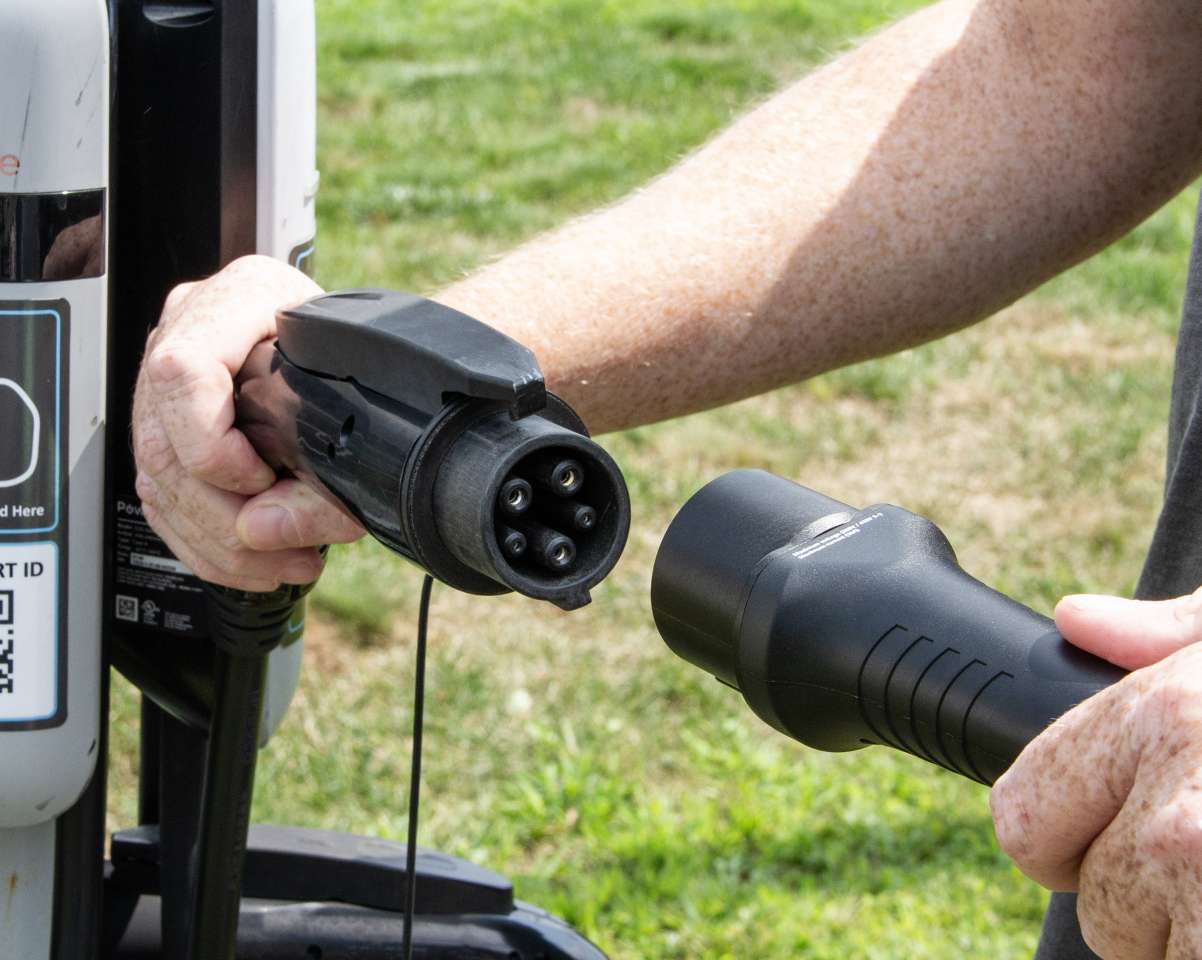
The Triplett Model TEV500 PRO Electric Vehicle Charger Test Kit tests charging stations using basic & advanced diagnostics. PE Pre-Test checks the PE conductor for the possible presence of dangerous voltage against earth. With the CP (Control Pilot) State rotary switch selector various vehicle states can be simulated. You can use the CP Signal output terminals to connect your oscilloscope to check the waveform and amplitude of the CP signal. CP Error “E” simulates the behavior of the station when there is an established short circuit between CP and PE. PE Error (Earth Fault) simulates interruption of the PE conductor. When the CCID TRIP Test Button is pressed, a connection between L1 and PE is established and CCID from the station should abort charging process. A phase indicator LED will illuminate when phase voltage on L1 is present at the charging connector. The Measuring Terminal Outputs L1, L2(N), PE and PP are directly connected to the L1, L2(N), PE and PP conductors of the tested charging station. You can use your digital multimeter for quickly viewing voltage readings on these lines. SAE J1772 complies with North American standards. Includes (1) IEC62196-2 Type 1 female to male adaptor/converter and pouch case.

Features:

  • Test charging stations for both basic & advanced diagnostic requirements
  • PE Pre-Test: Allows testing the PE conductor for possible presence of dangerous voltage against earth
  • Control Pilot (CP) State (Vehicle Simulation): With the CP State rotary switch selector various vehicle states can be simulated
  • CP Signal State Output: For use with an oscilloscope to check the waveform and amplitude of the CP signals
  • CP Error “E” simulation: Simulate the behavior of the station when there is an established short circuit between CP and PE
  • PE Error (Earth Fault) simulation: Simulates interruption of the PE conductor
  • CCID TRIP Test Button: When pressed a connection between L1 and PE is established and CCID from the station should abort charging process
  • Phase indicator LED: When phase voltage on L1 is present at the charging connector, the LED indicator will illuminate
  • Measuring Terminal Outputs L1, L2(N), PE and PP: Directly connected to L1, L2(N), PE and PP conductors of the tested charging station. It is allowed to use these for measuring purposes only and can be used with any Digital Multimeter for viewing voltage readings
  • SAE J1772 -Complies with North American standards

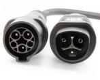
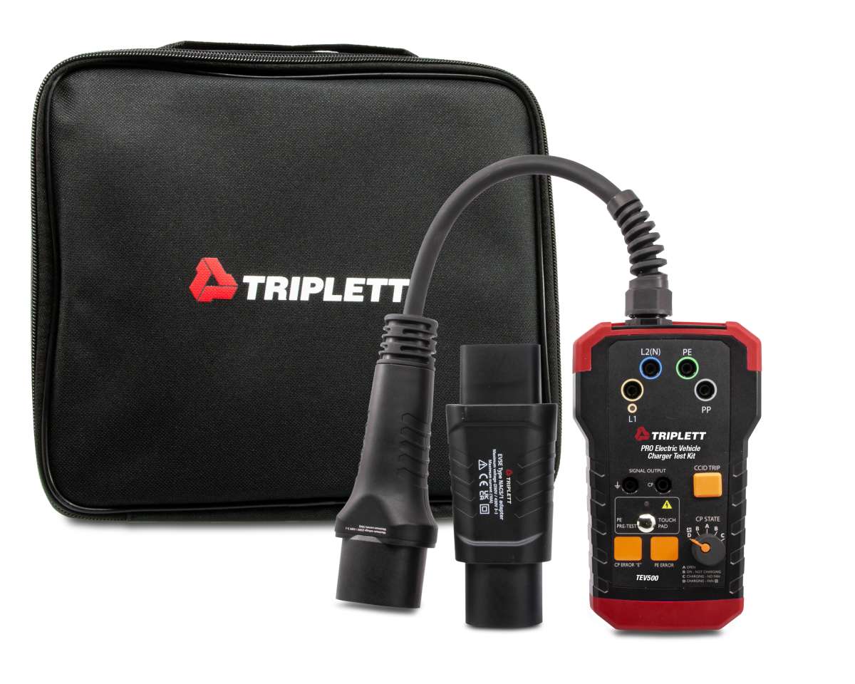
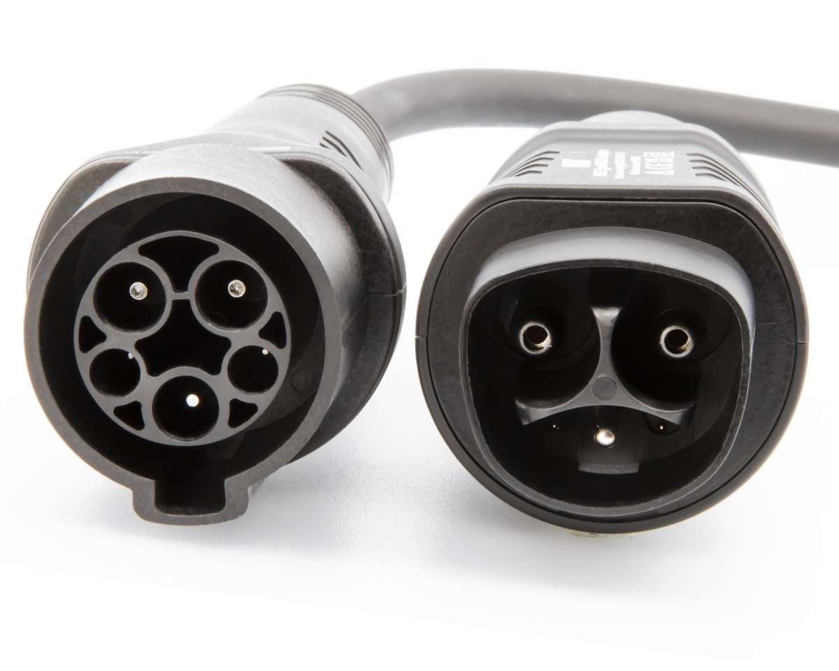
Includes: Includes (1) IEC62196-2 Type 1 female to male adaptor/converter and pouch case

Specifications
Input Voltage240V (Single Phase)60Hz
120V/208V (3-Phase) 60Hz
CP SimulationStates A, B, C, D
Error SimulationCP error “E”, PE (Earth Fault) Error
CCID TRIP simulationYes (>25mA @130V)
Test Connector TypeIEC62196-2 Type 1 male
(Male to Female Adaptor Included/Tesla)
Measurement CategoryCAT II 300V
PE Pre-Test:Yes
Test Cable Length9.8” (25 cm)
PowerPowered by Charging System
Dimensions6.9 x 4.2 x 2.8" (175.3 x 106.7 x 71.1mm)
Weight1.2lbs (544.3g)
Control Pilot (CP)State (Vehicle Simulation)
Vehicle StateState Description
AElectric vehicle not connected
BElectric vehicle connected, not ready to charge
CElectric vehicle connected, ready to charge,
ventilation not required
DElectric vehicle connected, ready to charge,
ventillation required
TEV500
Input voltageUL1/N = 120 V, UL2/N = 120 V, UL1/L2 = 208 V, 60 Hz (three-phase system) or UL1/N = 120 V, UL2/N = 120 V, UL1/L2 = 240 V, 60 Hz (single-phase system), ±10% voltage fluctuations from nominal
EV connector (EVC-13)SAE J1772 (Type 1, 5P single phase) for measuring purpose
Adapter SAEJ1772 to NACS for measurement purpose
Internal power consumption<1W
Operating temperature-20 to 40 degree C (-4 to 104F)
Storage temperature-20 to 40 degree C (-4 to 104F)
Operating Altitude2000 mtr (6562ft)
Weight641.5G (1.4lbs)
Safety standardsIEC 61010-1, Pollution Degree 2
Measurement categoryCAT II 300V
IP protection classIP40
Functions
Indication LEDsL1, PE error
CP StatesA, B, C , D
CP Error “E”On / Off
PE ErrorOn / Off
GFCI TestYES, test resitor connected between L1 and PE
PE Pre-Test (typical)YES
Outputs (for test purpose only)
Measuring terminalsMax. 250 V 50/60 Hz, CAT II 300 V
L1, L2/N, PE
CP signal output terminalsApprox. ±12 V (under normal conditions), in case of wrong wiring or error of the charging station these terminals can be hazardous ≥ max. 250 V against PE

Warranty: 2yrs