Mold Inspection Consulting and Remediation Organization
Since 2006
close menu

Triplett TEV300 Electric Vehicle Charger Test Kit

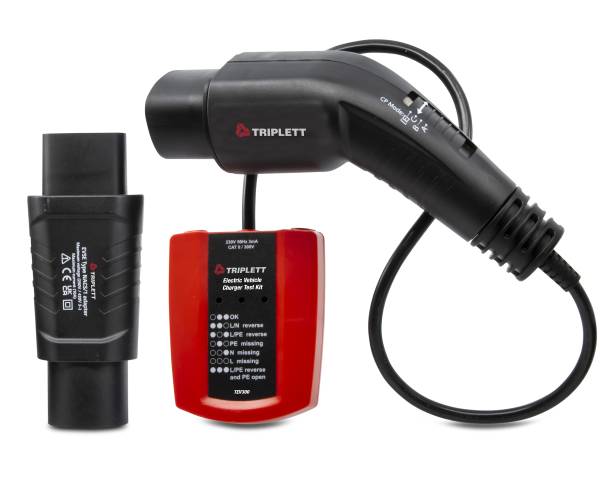
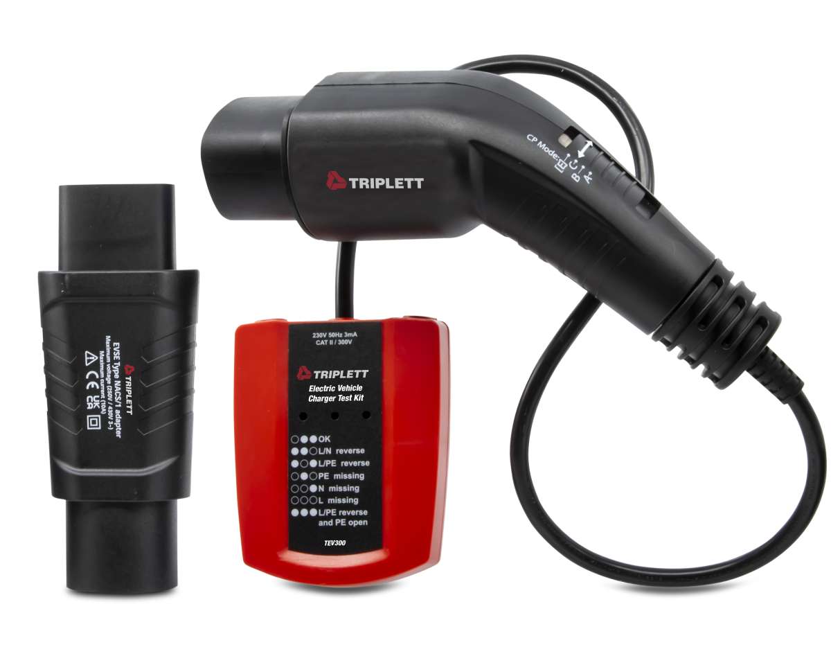
The Triplett Model TEV300 Electric Vehicle Charger Test Kit provides fundamental wiring testing for EV charging systems with LED GO/NO GO that indicates the status of the charger output socket.

More info

Triplett TEV300 Electric Vehicle Charger Test Kit
Roll over image to zoom Click image to expand
  • Triplett TEV300 Electric Vehicle Charger Test Kit
  • Triplett TEV300 Electric Vehicle Charger Test Kit
  • Triplett TEV300 Electric Vehicle Charger Test Kit
  • Triplett TEV300 Electric Vehicle Charger Test Kit

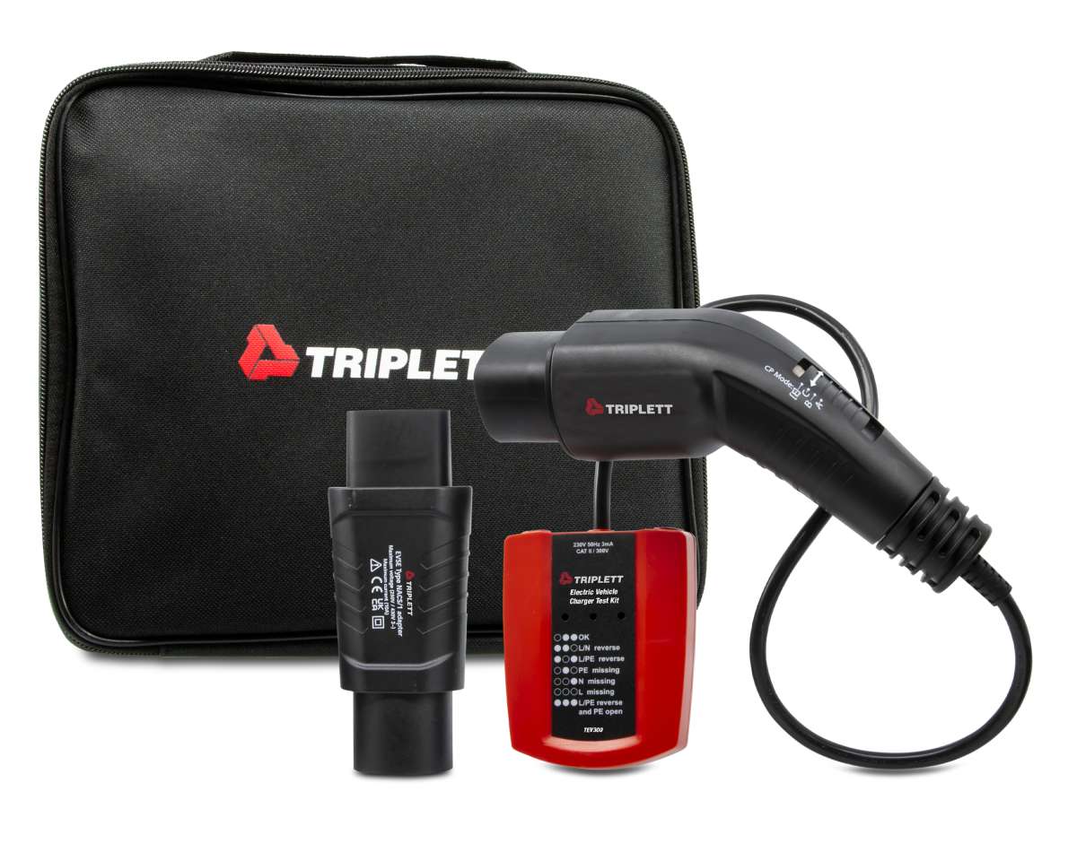
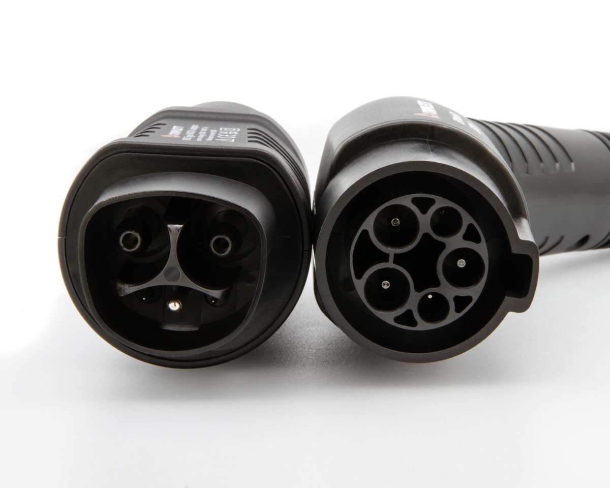
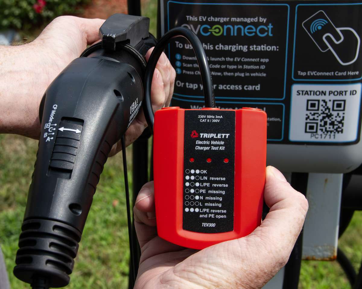
The Triplett Model TEV300 Electric Vehicle Charger Test Kit provides fundamental wiring testing for EV charging systems with LED GO/NO GO that indicates the status of the charger output socket. An LED indication chart provides simple socket inspection conditions and does not require a vehicle connected to it. The Proximity Pilot (PP) State (Cable Simulation) simulates 20A current capability between PP and PE conductors. A built-in Control Pilot (CP) State (Vehicle Simulation Switch) can simulate vehicle states with different resistances connected between CP and PE conductors. CP Error “E” simulates the behavior of the station when there is an established short circuit between CP and PE. Complies with EMC Directive (2014/30/EU), the Low Voltage Directive (2014/35/EU), and EN61010-1 standards. Includes (1) IEC62196-2 Type 1 female to male adaptor/converter and pouch case.

Features:

  • Provides fundamental wiring testing for EV charging systems with LED GO/NO GO indication
  • Indicates the status of the charger output socket (vehicle side)
  • LED Indication and Chart Provides simple socket inspection conditions
  • Proximity Pilot (PP) State (Cable Simulation) - Simulates 20A current capability between PP and PE conductors
  • Built-In Control Pilot (CP) State (Vehicle Simulation Switch - Different vehicle states can be simulated: Vehicle states are simulated with different resistances connected between CP and PE conductors
  • CP Error “E” simulation: Simulate the behavior of the station when there is an established short circuit between CP and PE
  • Complies with EMC Directive (2014/30/EU), the Low Voltage Directive (2014/35/EU), and EN61010-1 standards

Includes: Includes (1) IEC62196-2 Type 1 female to male adaptor/converter and pouch case

Specifications
Input Voltage230V/400V
Network TypesTN, TT
Measuring TerminalsL1, N, PE Max. 230/400V 50/60 Hz
Fixed ConductorType-2-connector, fixed to device
Included AdaptorIEC62196-2 Type 1 male
(Male to Female Adaptor Included/Tesla)
Socket/Test Lead ColorsL1, N, PE in 3-wire-cable
CP and PP State SimulationYes
Measurement CategoryCAT II 300 V
IP RatingIP40
Test Cable Length9.8” (25 cm)
PowerPowered by Charging System
Dimensions24” x 2.8”x 2.4” (600 x 70 x 60 mm)
Weight12.8oz (365g)
Control Pilot (CP)State (Vehicle Simulation)
Vehicle StateState Description
AElectric vehicle not connected
BElectric vehicle connected, not ready to charge
CElectric vehicle connected, ready to charge,
ventilation not required
ECP Error
TEV300
Input voltageUL1/N = 120V, 60 Hz, +/- 10%
EV connector (EVC-13)SAE J1772 (Type 1, 5P single phase) for measuring purpose
Adapter SAEJ1772 to NACS for measurement purpose
Internal power consumption<1W
Operating temperature-20 to 40 degree C (-4 to 104F)
Storage temperature-20 to 40 degree C (-4 to 104F)
Operating Altitude2000 mtr
Weight310.5G (.7lbs)
Safety standardsIEC 61010-1, Pollution Degree 2
Measurement categoryCAT II 300V
IP protection classIP40
Functions
Indication LEDsL1, N, PE for checking correct function and wiring
CP StatesA, B, C
CP Error “E”On / Off
PE Errorn.a.
GFCI Testn.a.
PE Pre-Test (typical)n.a.
Outputs (for test purpose only)
Measuring terminalsMax. 250 V 50/60 Hz, CAT II 300 V
L1, L2/N, PE
CP signal output terminalsn.a.

Warranty: 2yrs